 HOTLINE:+8613974960765 +8618507312158 HOTLINE:+8613974960765 +8618507312158
— Product —
 Service Hotline +8613974960765
 Email:susie@hnljpump.com
Mobile:+8618507312158
TEL:+8613974960765
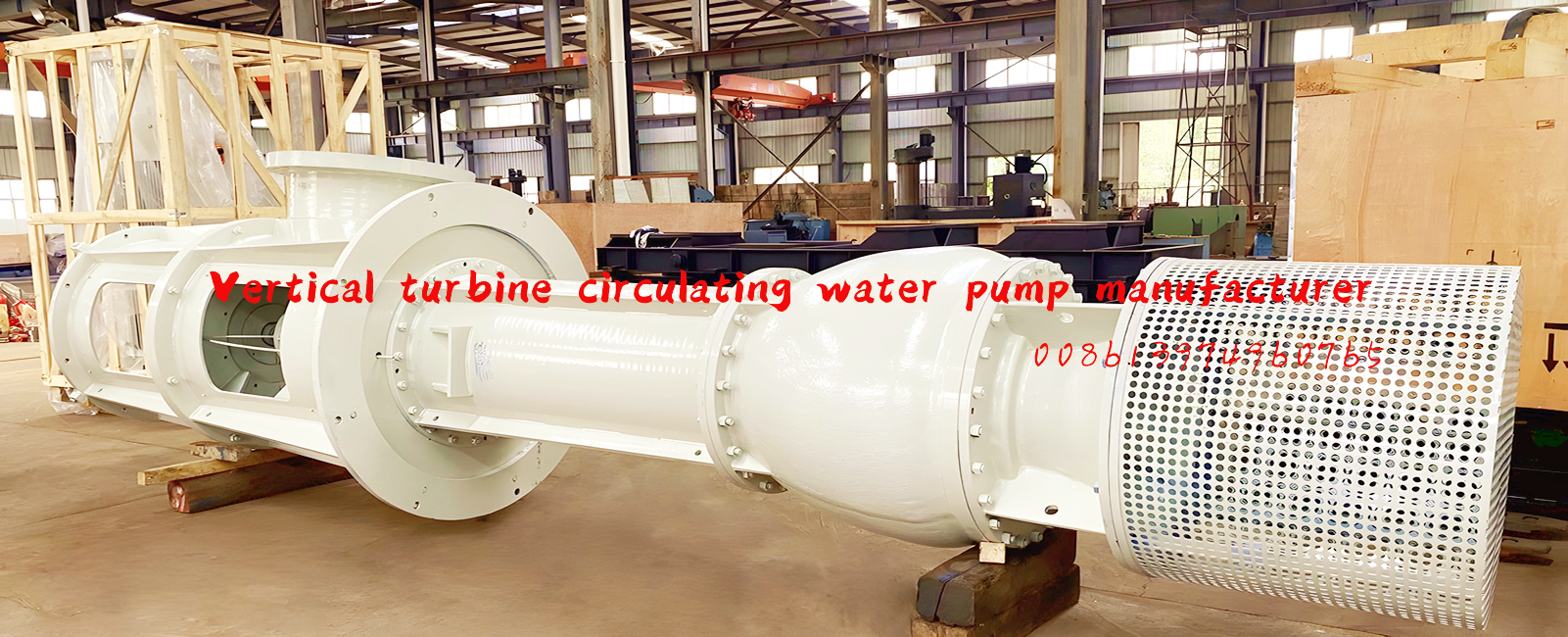
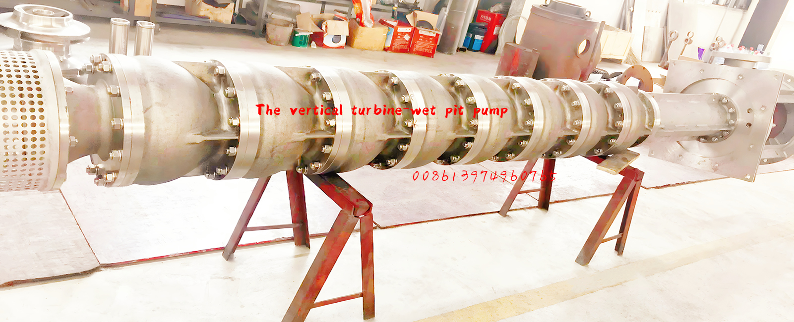
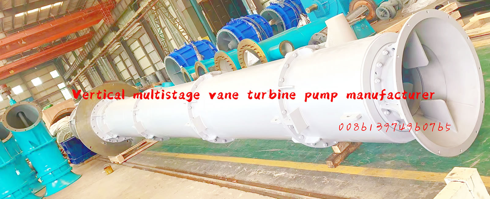
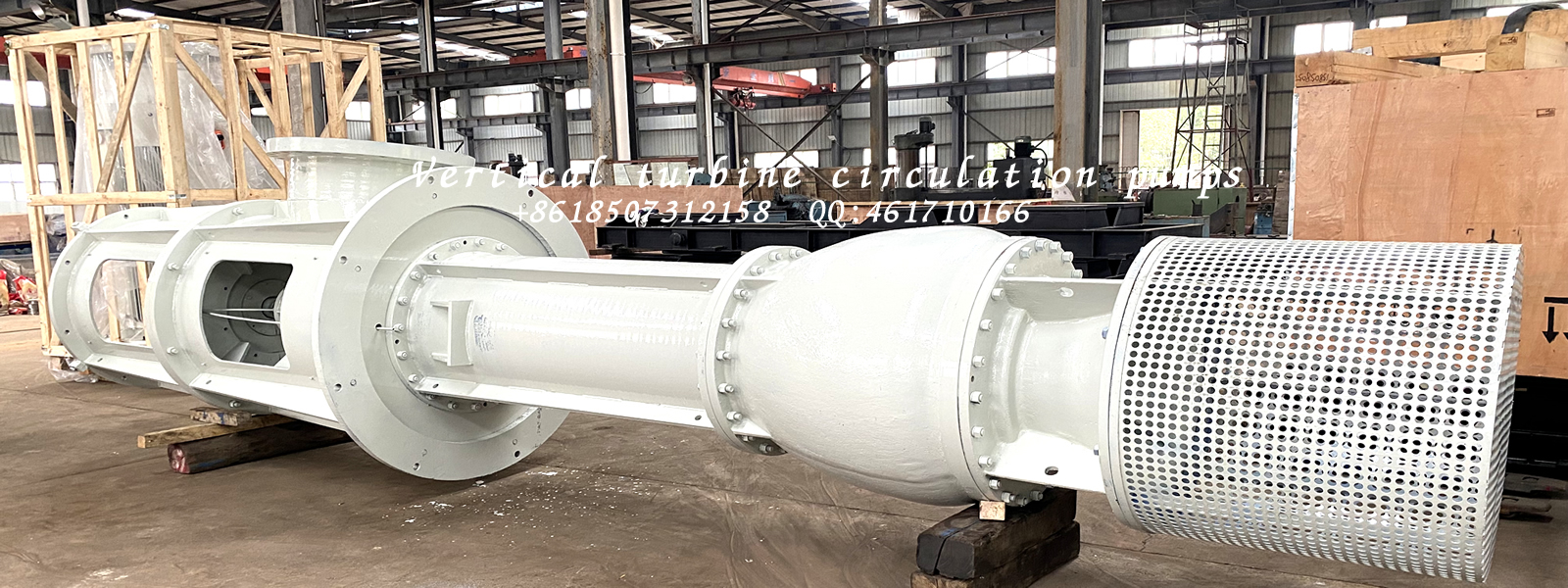
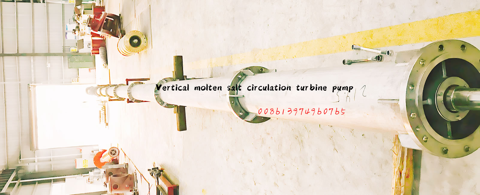
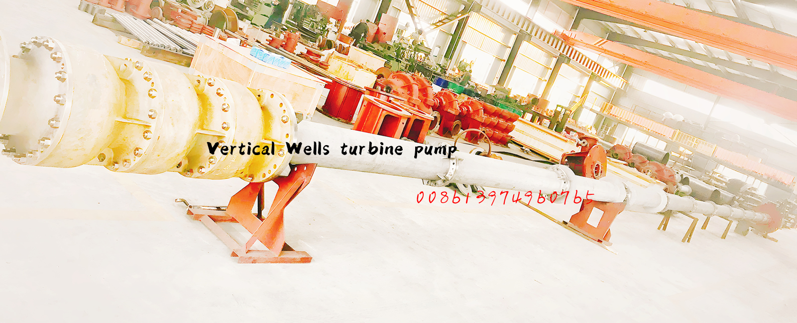
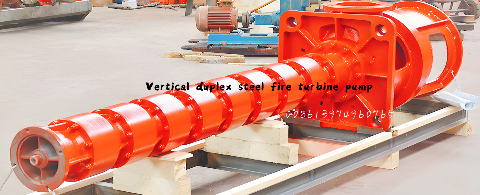
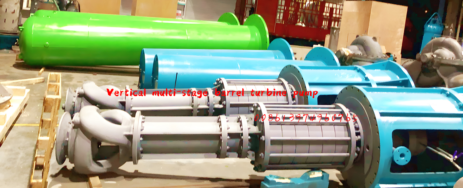
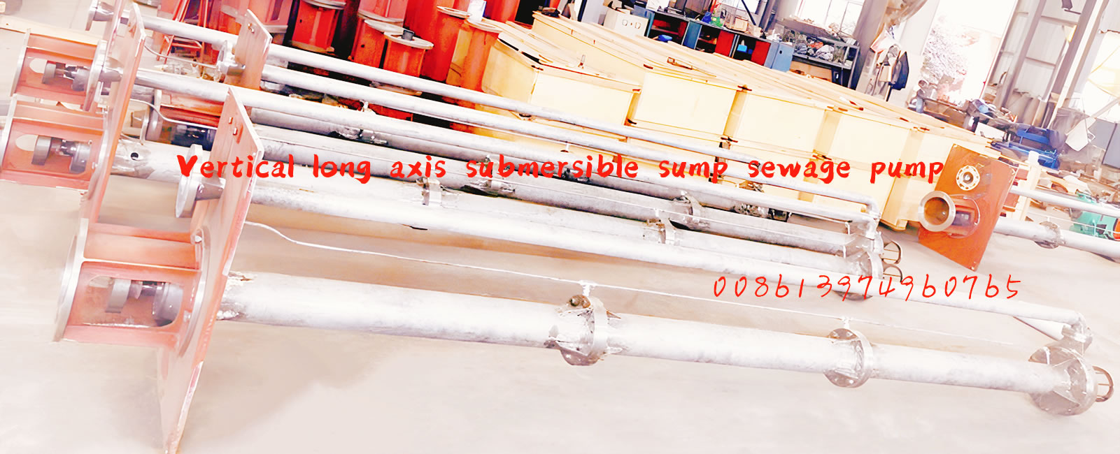
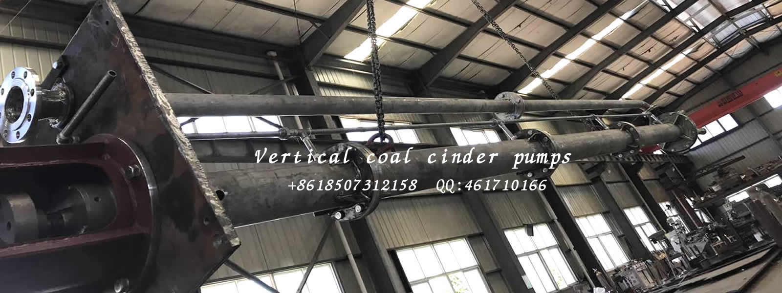
Vertical Wet Pit Pumps
发布时间:2021/3/26 15:14:56 人气: [content:visits]
The use of vertical turbine pumps for well water is common. Deep-set well pumps range in length from around 100 inch all the way up to around 1,000 inch, and settings between 200 and 400 inch are common. Deep well pumps are used for irrigation water in many parts of the country, as well as for drinking water supply.

 Pumps")
 Pumps")
General
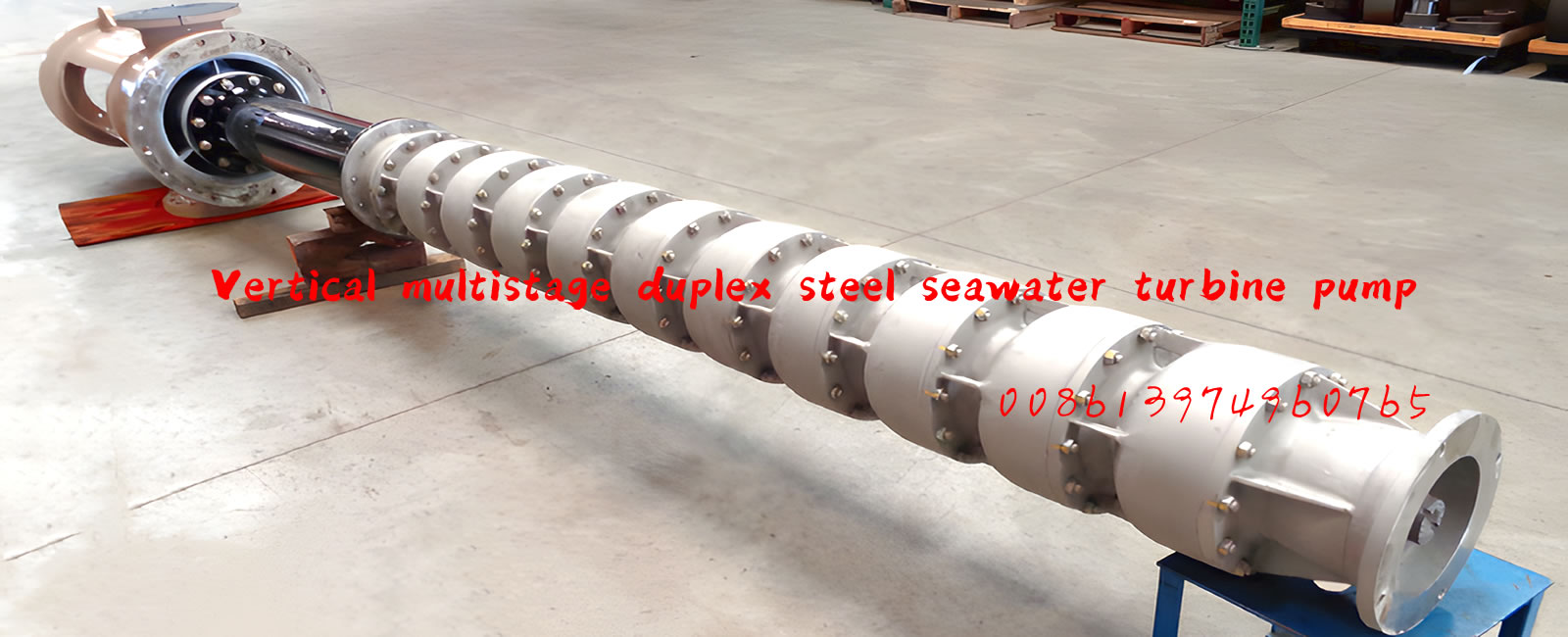
Deep Well Vertical Turbine (Borehole) Pumps is a new product produced according to requirement of market, it adopts the best and advanced technology in its design and manufacture. The pumps are not only reliable、 high-efficiency, but also easy for installation and maintenance.
The vertical pump of these series are according with corporation standard Q/ACXR001《Vertical long-shaft pump》
The manual is written according to GB9969.1《General rules for industrial product usage manual》 .
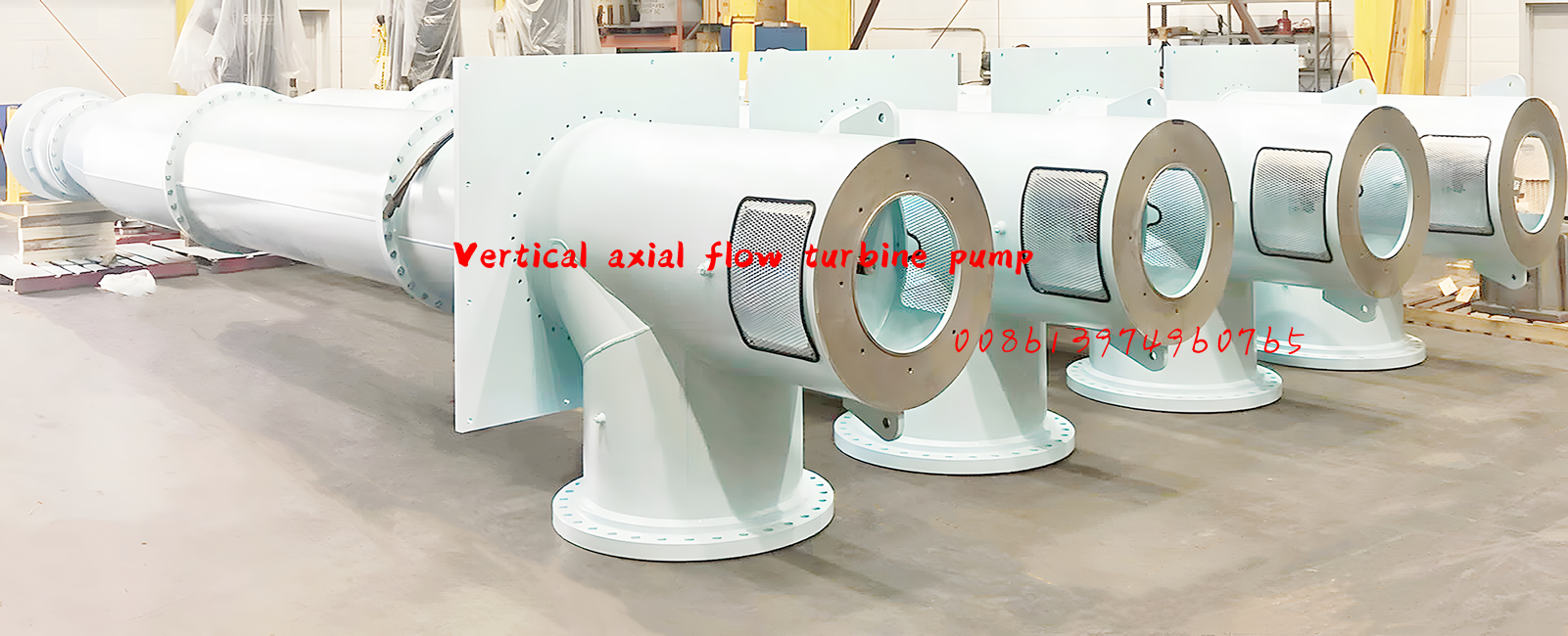
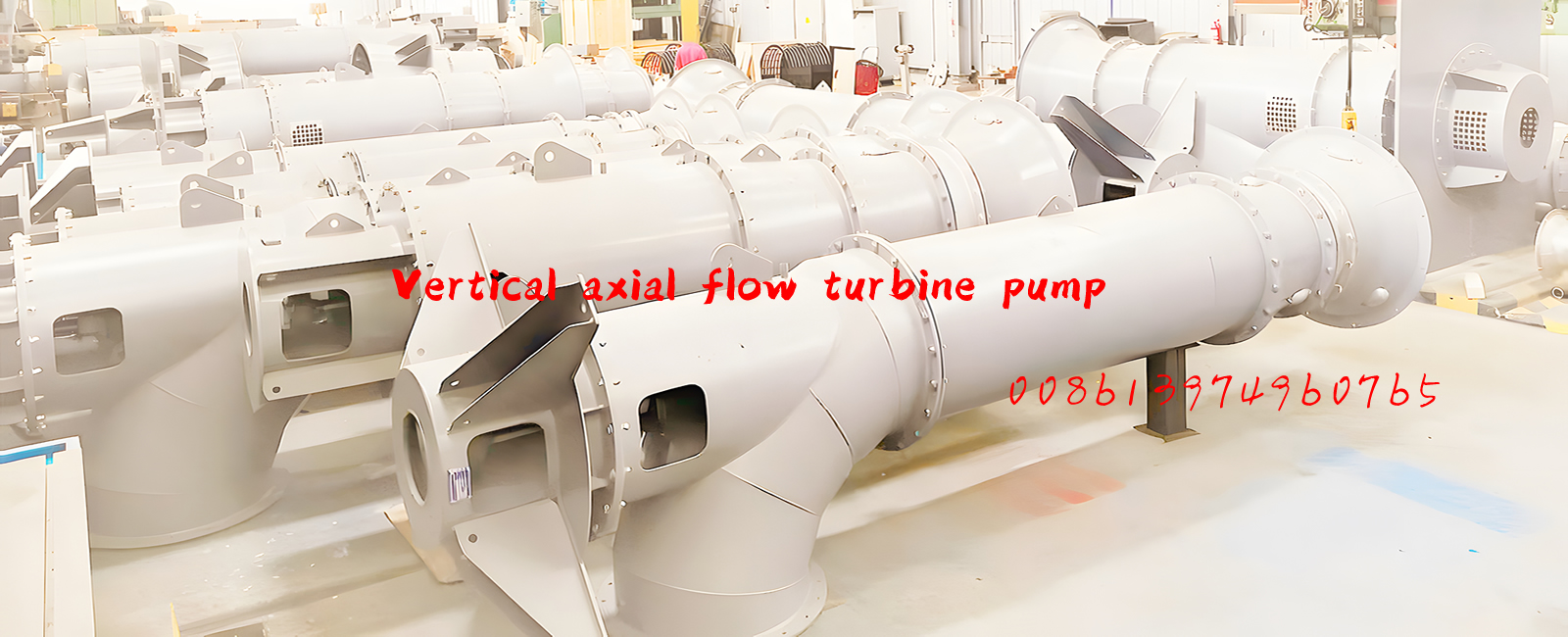
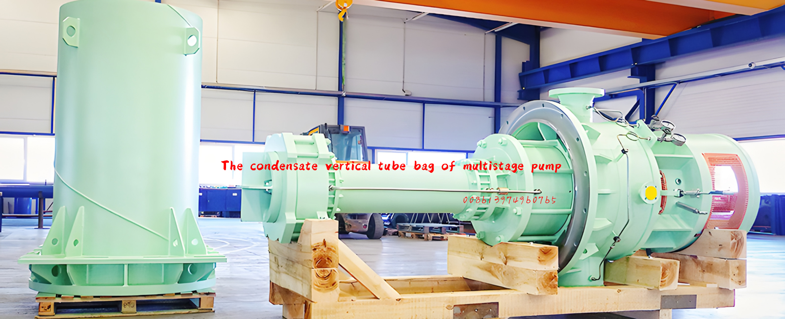
Applications Conventional Steam, Combined Cycle, Integrated Gasification Combined Cycle, Cooling Towers, General Offshore, Crude Handling and Treatment, Heavy Oil and Upgrading, Water Injection, Water Handling and Treatment, Circulating Water, Deep wells and sumps, agricultural irrigation, municipal water supply systems, water transfer, dewatering, condensate extraction, oil & gas productionGeothermal Energy.
Usage
Deep Well Vertical Turbine (Borehole) Pumps are widely used to feed and drain water in clean-water factory、 waste-water work、 mineral、 Power station、 steel and metallurgical industry、 irrigation in countryside and hydraulic project.
Working condition
Speed: 590、740、980、1480和2980r/min
Voltage: 380V、6000V、10000V
Outlet Diameter: 100~1000mm
Capacity: 60~8400m3/h(Design Point)
Head: 12.5~94.5m(Design Point)
Temperature: ≤80℃
Permitted delivering medium: Clear water、 Waste-water with little grain (such as iron filings sand and coal powder etc.)、 Industrial waste-water with corrosion and Sea water.
Nomenclature
150LC3-90A-L
150—Outlet diameter of pump is 150mm
LC—Deep Well Vertical Turbine (Borehole) Pumps
3—Impeller stage number is 3 (omit when the stage number is 1)
90—The design head without cutting is 90m
A—The cut code of impeller outer diameter
L—Submerged depth(L≤18m)
Material of main parts
 Pumps")
Remark: Other materials can be used according to user’ s requirement.
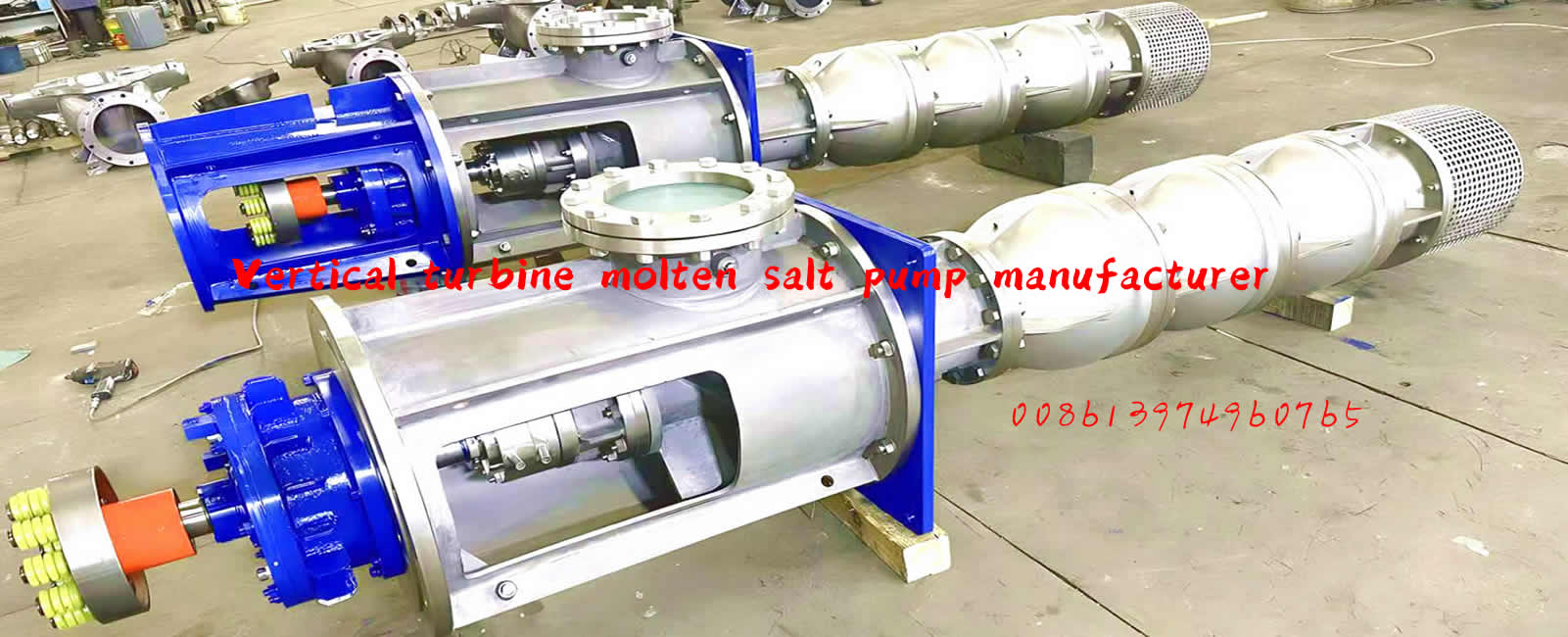
The inlet of Deep Well Turbine (Borehole) Pumps is upright down、outlet is level,the pump and the motor is connected directly and installed in the same foundation.Looking at the impeller from the motor end, it should rotate counterclockwise.
The main features
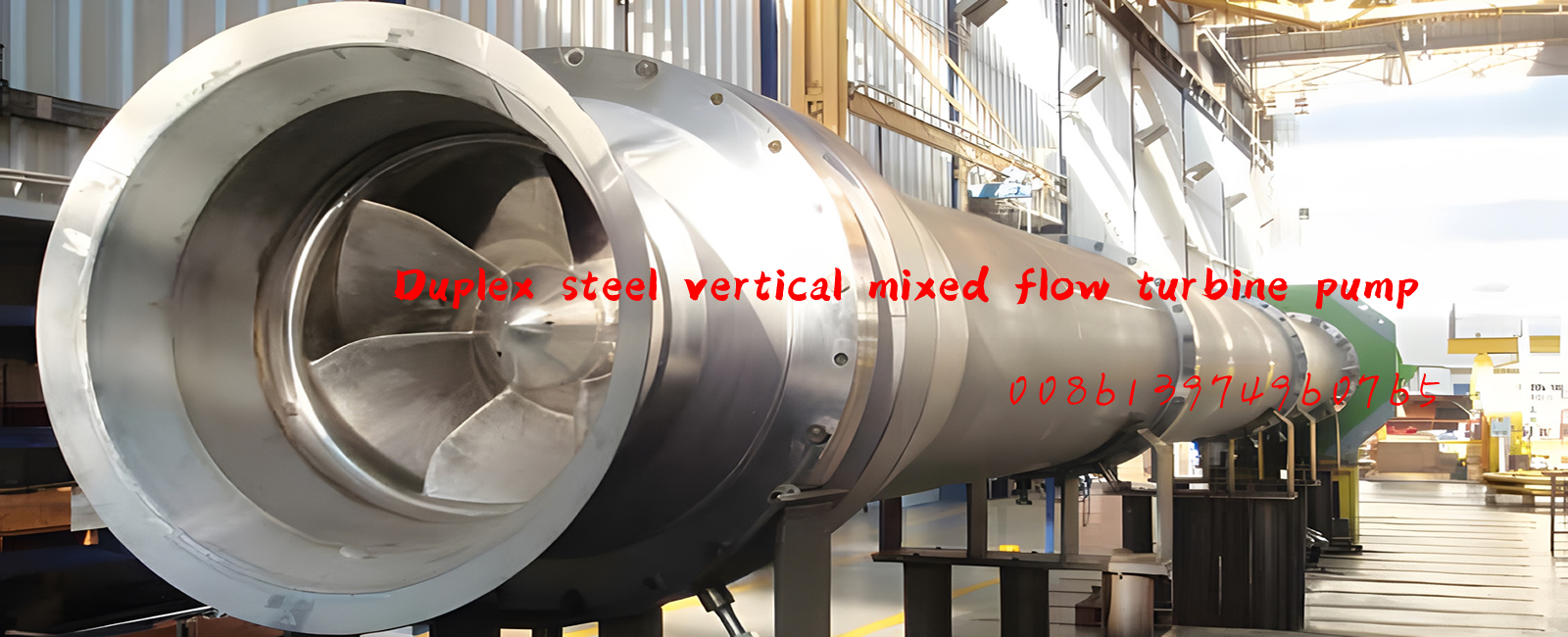
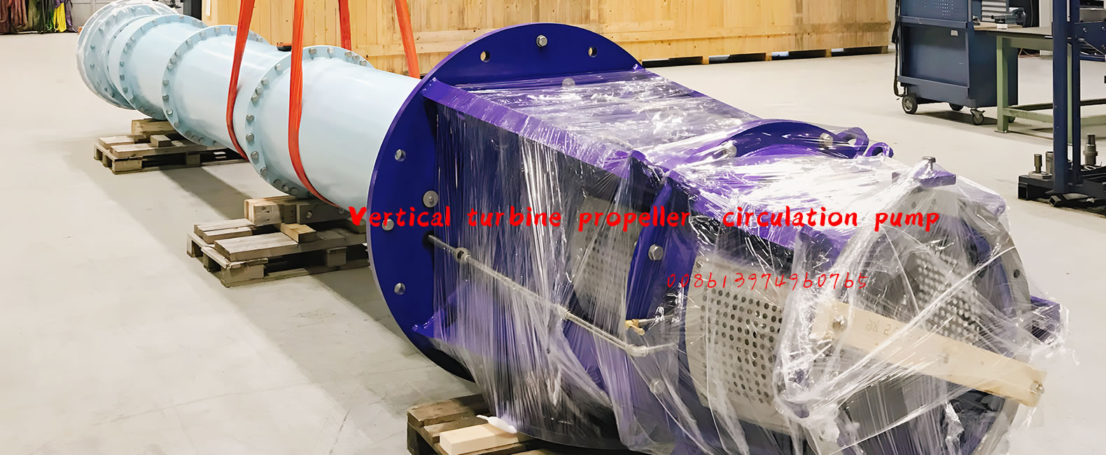
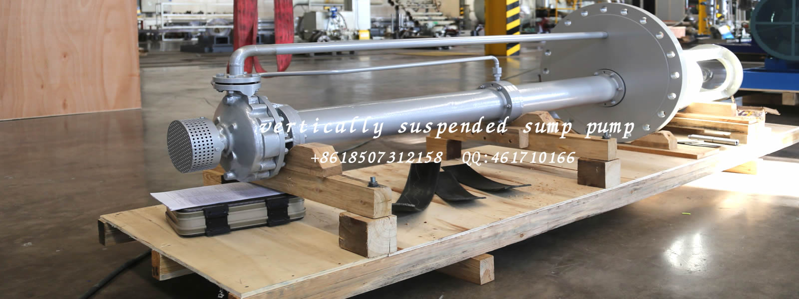
The pump are made under the design with good hydraulic model. It has a superior performance. The impeller and the guide blade has good corrosion resistance,which make the impeller and other easy-worn parts has a long-life. The pump is stable and safe in operation and has a high save-energy. The filter is installed in pump outlet with proper opening holes,this not only prevent the pump from damage because of the impurity entering the pump but also reduce the inletloss and increase the pump efficiency.
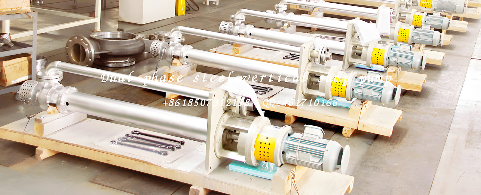
Impeller adopts balance holes for balancing its axial force and there is replaceable seal ring in its front and back cover board for protecting impeller and pump casing.Middle shaft、column pipe and protective pipe are multilevel burl,the connection of middle shaft adopts adapter coupling technology,the column pipe may be less or more according to user’s requirement to fit the different depth.Impeller and diffuser casing are multi-stage to fit the different Head.The column pipe is connected by flange with guide bearing in the middle,the guide bearing adopts PTFE、Jinlong bearing or thordon bearing and the shaft has a protective pipe,when the pump deliver sewage,the guide bearing should have external cool lubricatin gwater.
The remaining axial force of pump and the weight of rotor parts is borne by thrust bearing in motor seat or motor with thrust bearing. The thrust bearing is lubricated by dilute oil and cooled with external water . The thrust bearing can have element for monitoring temperature.
Pump shaft seal adopts packing seal, there is replaceable shaft sleeve in shaft seal and guide bearing to protect shaft, it is convenient to adjust axial location of impeller by nut in bearing parts upper end or pump coupling.
Pump can be quipped with controller which can automatically start and stop pump according to liquid level, give an alarm for over loading and control many pumps in long-distance. There is automatic exhaust system for pump with diameter over 500mm.
Configuration Figure :
 Pumps")
Assembly and disassembly
1. Preparation before assembly
1.1 Check every part before assembly, ensure there is no defect, and clean all the parts.
1.2 Check the cooperating parts: include key and shaft、 key and impeller; key、 clasp、adapter coupling and shaft; impeller、 shaft sleeve、 adapter coupling and shaft、 the radial clearance between the shaft sleeve and guide bearing is 0.15~0.25mm.
2. Part sassembly
2.1 Fix the seal ring on suction bell and diffuser separately with screws.
2.2 Fix guide bearing on both guide bearing support and diffuser, fix packing lining on stuffing box, don’t forget to fix key and space ring.
2.3 Small installing for thrust bearing parts: Fix oil-pail in the bearing body, fix outer ring of thrust bearing in bearing body and inner ring in rotating sleeve, then fix rotating sleeve in bearing body and finally fasten the bearing cover in the bearing body.
2.4 Middle shaft assembly: Knot shaft sleeve in the middle shaft, fix space ring and fasten with screw
2.5 Middle shaft assembly: Knot shaft sleeve in the middle shaft, fix space ring and fasten with screw.
3.General assembly
Pump can adopt vertical and horizontal assembly
3.1 Fix shaft sleeve、 key and last stage impeller in impeller shaft, then fix it in the last stage
diffuser.
3.2 Fix space ring、 next stage shaft sleeve、 diffuser、 key and impeller . repeat the above
process until the second impeller are completely installed.
3.3 Fix space ring、 shaft sleeve 、 first stage diffuser、 first stage key、 impeller, stop washer 、 locking impeller nut、 elbow and filter.
3.4 Fix key and adapter coupling in middle shaft orderly, connect impeller shaft with middle shaft by half snap ring, fix space ring in slot. Fix seal o-ring in last stage diffuser, fix guard column and water pipe, fix guide bearing bracket with screw (with seal o-ring in bracket). When vertical assembly, lift pump in pit and support it on baseboard of water pipe with channel steel. fix each stage middle shaft、 guard column 、 water pipe、 guide bearing bracket、 driven shaft、 adjusting guard column and adjusting water pipe.
3.5 Connect discharge elbow and adjusting water pipe; fix seal o-ring in stuffing box, aim adjusting guard column to fix stuffing box in discharge elbow, then fix stuffing cover.
3.6 Fix key in driven shaft , fix thrust bearing parts on discharge elbow, then fix ball nut.
3.7 Fix pump coupling key and pump coupling.
3.8 Fasten motor seat on discharge elbow.
3.9 Lift the rotor by adjusting the two ball nut of thrust bearing, the lift level is 1/2 total beating level of the rotor, the blocking is not allowed.
3.10 Lift the rotor by adjusting the two ball nut of thrust bearing, the lift level is 1/2 total beating level of the rotor, the blocking is not allowed.
If pump's thrust force is borne by motor, there will no installation of thrust bearing parts (in the 3.6 item), lift the rotor through the adjusting disk of pump coupling, the lift level is 1/2 total beating level of the rotor.
Attention:
1. In the above assembly process, some small parts such as key、 block water ring and seal o-ring in the shaft sleeve can be easily lost or assembled disorderly, this should be take great attention.
2. When deliver clean water, if where is no cool lubricating water for guide bearing, then guard column can't be installed.
3. If the lift height is not enough, hang the installed parts in the pump pit to install and before putting them in the pump pit, fix filter and also fix lubricating water pipe of guide bearing.
4.Disassembly
The order of disassembly is on the opposite side of the assembly, pay attention to the following while disassembly.
4.1
Mark the relevant cooperating surface that will be convenient for next assembly.
4.2
Prepare some cases to put the disassembled parts to prevent them from losing and colliding.
Don't put the fasten parts together, because their material is different according to different using condition.
4.3
Prepare thin anti-rust oil to coast the manufacturing surfaces.
4.4
Re-use of seal-ring、 paper washer、 rust-locking parts、 spring washer and packing are not allowed.
Installing
Pump installing quality is affected directly on pump running and life, so installing and adjusting must be strict.
1.Foundation 、 Pipeline and Pump house
We suggest that user should invite the special designing people and unit to design foundation、pipeline and install pump.
1.1 The foundation must be firm and it can bear the vibration of pump and support pump set forever, the foundation must have the ability to bear the weight that is 1.5 times of the pump set (include motor). Usually the pump foundation is concrete foundation with bolts hole in the foundation, while install the pump, first fix foundation bolts, then make the second pour.
1.2 Don’ s use pump as pipe bracket, all pipes should be supported separately; the pipe should be short as possible as it can, and also reduce elbow in the pipe to avoid more loss; usually the discharge pipe is one standard larger than the outlet, among pump and pipe it should install gate valve and check valve (when head is less 20m, the valve can omit), the diameter of gate valve should be not less than the diameter of pipe, the check valve is installed between gate valve and pump .
1.3 The pump should be installed properly to have proper space for operating、 disassembling and
inspection , also the pump house should have enough device and space for lifting; when pump is driven by motor, it will be influenced by outside environment, so the house should be ventilated, It can't be too hot or too wet. When pump is used outside, adopt outside motor.
Attention:The pump pipeline system and foundation etc. are not designed by our company, so we are not responsible for it, but we may offer some suggestion about the design and operating.
2.Preparation before installing
2.1
Check the equipment to ensure it well and comp
2.2
Clean the foundation, check the hole dimension of foundation bolts, check the pump set level.
2.3 Prepare installation tool and lift equipment.
3.Installing technical requirement
3.1
Check and adjust center degree of motor shaft and the pump to ensure two shaft in a direct
line.
3.2
Ensure the pump coupling and motor coupling with clearance stipulated in assembly drawing.
3.3
The pipeline should have its own bracket to avoid all weight on pump.
3.4
After installing pipe, adjust them again according to state process.
3.5 Between flange and pipe, it can't leakage gas.
4.Installation and Calibration
4.1
The pump suspends on foundation bolts, then use nuts and gasket to fix, ensure the foundation bolts suspend in obligated hole in pedestal freely. Between pump pedestal and foundation, use couple wedge to adjust. Put gradienter on pedestal , adjust level with wedges , (less than 0.05mm/m ), tighten the nuts on foundation bolts suitably to prevent the pump moving .
4.2
Use cement to pour the pedestal and the hole of the foundation bolt.
4.3
After the cement dry, examine whether the basement and the eye of the foundation bolt are loose.
4.4
Place the pump set in the common base, prepare cooling water pipe.
4.5
Lift the rotor by adjusting the top of thrust bearing or adjusting nut in pump coupling, the lift level is 1/2 total level of the rotor , the blocking is not allowed.
4.6
Fix motor with coupling on the motor pedestal, adjust the coaxial degree of the motor and the pump by adjusting bolts.
4.7
Check the pulse of coupling, the radial pulse and end pulse of coupling of pump and motor should be less than 0.1mm. For flexible coupling, the radial deviation of pump and motor should be less than 0.1mm, the end surface clearance meets the requirement in the table and the irregularity degree along circumference should be less than 0.1mm.
The outer diameter of coupling(mm) | 170 | 190 | 220 | 260 | 330 | 410 | 640 |
The end clearance of two coupling(mm) | 4 | 4 | 4 | 5 | 6 | 7 | 8 |
4.8
After installing pipeline and the pump is running, check and adjust the pump concentricity again.
4.9
After the pump test-running for 2-3 hours, make the final check, if there is no abnormal trouble, then the installation is right.
Attention:
1.During installing, all eyes of the hole should be covered to prevent dirty things entering the pump.
2.Ensure the rotating direction of the pump: the pump is anti-clockwise viewed from the motor end , the incorrect rotating direction will cause the pump damaged and the
body injure.
Starting、RunningandStopping
1.Inspection and preparation before starting
1.1
Take the dirt things on the pump away and make the site clean, check to see if the foundation bolt is loose.
1.2
Check to see if the submerged depth is expected.
1.3
Check to see if there is packing in the pump.
1.4
Check the supply of cooling water , the cooling-water should be clean soft water, the cooling water capacity for thrust bearing is 0.3~ 0.5m3/h, the pressure is 0.1~0.2MPa, the capacity and the pressure of the guide bearing refer to the appendix table.
1.5
Ensure the pump and motor to be lubricated, the lubricating-oil type is L-AN32 mechanical oil, the oil level is up or down 2mm of the centerline of the oil-meter, the lubricating for the motor follow the installation manual of the motor.
1.6
Before starting, turning the rotor, it should be flexible.
1.7
Check if the rotating direction of the motor is right: the pump is anti-clockwise viewed from the motor end.
1.8 Check if the motor、 other electric equipment and instruments are normal.
2.Starting
2.1
Shut off the outlet gate valve and the pressure meter plug, open valve in cooling water pipe.
2.2
Check the capacity and pressure of cooling water, only when it meets the requirement, pump can be started.
2.3
When the capacity and pressure meet the requirement and more than 3 minutes, then start motor, when the pump rotates in normal speed, open the pressure meter plug and open the gate valve in the discharge pipeline gradually and adjust to needed working condition. when the gate valve on the discharge pipeline is in close, the continuous working time of the pump should not be more than 2 minutes.
2.4
Tighten the nut on the packing cover appropriately to let liquid flow as drops, pay attention to temperature of packing box.
Attention:
1.When the capacity and pressure meet the requirement and more than 3 minutes, then start motor, when the pump rotates in normal speed, open the pressure meter plug and open the gate valve in the discharge pipeline gradually and adjust to needed working condition. when the gate valve on the discharge pipeline is in close, the continuous working time of the pump should not be more than 2 minutes.
2.
Don’t make too tight to packing cover, little leakage can lubricate packing but no leakage will burn packing and scratch shaft sleeve.
3.
When pump deliver sewage, the guide bearing should have cooling lubricating water. If the capacity and pressure of cooling lubricating water is not enough, it will affect the pump’ s life severely. The water passing through the guide bearing should be kept more than 3 minutes, don’t close the cooling water until pump stops running completely.
4.
When deliver clean water, the guide bearing may have no cooling lubricating water, but the guard column should cancel.
3.Running
3.1
The temperature of bearing should be 35℃ less than outer temperature, the Max temperature should below 75℃.
3.2
During the running must watch the date of instrument、 the temperature of bearing、 the leakage of the packing 、 the vibration and noise of the pump, if the condition is not normal ,treat it in time.
3.3
Make a regular check of capacity and pressure of lubricating water, the water must be kept always while pump running, also make a regular clean to the filter.
3.4
The normal leakage in packing box is 20~30 drops per minutes.
3.5 Pay attention to bearing temperature of the motor.
3.6
The lubricating oil level should heap in normal level that it can't be too high or too low, when the level is too low, add the grease time, usually for first time oil should be replaced completely for running 300 hours, next time replace oil for very 3000 hours running, users can also decide it according to actual condition and past experience.
Attention:
1.
The pump is not allowed to run when the submerged depth is not enough to prevent NPSH from damaging pump.
2.The continuous running is not allowed when the capacity is less 30% than that of design capacity, unless add bypass pipe.
3.
The continuous running is not allowed when the capacity is more 120% than that of design capacity otherwise it will bring NPSH and excessive power to motor.
4.Forbid to increase the pump speed.
5.
During pump running, if there is abnormal noise or other troubles it should be stopped to check at once.
4.Stopping
4.1 Close plug of pressure meter.
4.2 Shut off the outlet pipeline valve gradually.
4.3 Cut off electricity
4.4 Close the cooling water after pump stops running
completely.
If the pump will be stopped for a long time, it is necessary to disassemble and clean pump and then greasing and packing.
The capacity and pressure for guide bearing
Pumptype | Pressure | Capacity(m3/h) |
150LC-23、23A | 0.3~0.4 | 0.8~1.0 |
150LC-30、30A | 0.4~0.5 | |
150LC2-46、46A | 0.6~0.7 | |
150LC2-60、60A | 0.7~0.8 | |
150LC3-90、90A | 1.0~1.1 | |
200LC-19、19A、23 | 0.2~0.3 | |
200LC2-38、38A、46 | 0.3~0.4 | |
200LC3-57 | 0.5~0.6 | |
200LC3-69 | 0.6~0.7 | |
200LC4-92 | 0.8~0.9 | |
250LC-20、20A,250LC-32、32A | 0.2~0.3 | 1.2~1.4 |
250LC2-40 | 0.3~0.4 | |
250LC2-63、63A | 0.4~0.5 | |
250LC3-95、95A | 0.7~0.8 | |
300LC-25、25A,300LC-39、39A | 0.2~0.3 | |
300LC2-50 | 0.4~0.5 | |
300LC2-78、78A | 0.5~0.6 | |
350LC-19、19A,350LC-30、30A、30B | 0.2~0.3 | 1.4~1.6 |
350LC-48、48A、48B | 0.3~0.4 | |
350LC2-60、60A、60B | 0.4~0.5 | |
400LC-25、25A,400LC-39、39A | 0.2~0.3 | |
400LC2-50、50A | 0.4~0.5 | |
400LC-62、62A、62B | 0.3~0.4 | |
450LC-17、17A,450LC-27、27A、27B | 0.2~0.3 | 1.6~1.8 |
450LC-43、43A、43B, | 0.3~0.4 |
450LC2-54、54A | 0.4~0.5 | |
500LC-20、20A,500LC-31、31A、31B | 0.2~0.3 | 1.8~2.0 |
500LC-50、50A、50B | 0.3~0.4 | |
500LC2-63、63A | 0.4~0.5 | |
600LC-25、25A | 0.2~0.3 | |
600LC-39、39A、39B,600LC-62、62A、62B | 0.3~0.4 | |
700LC-20、20A | 0.2~0.3 | 2.2~2.4 |
700LC-32、32A、32B,700LC-50、50A、50B | 0.3~0.4 | |
800LC-24、24A | 0.2~0.3 | |
800LC-38、38A、38B,800LC-60、60A、60B | 0.3~0.4 | |
900LC-21、21A | 0.2~0.3 | 2.6~2.8 |
900LC-33、33A、33B,900LC-52、52A、52B | 0.3~0.4 | |
1000LC-25、25A | 0.2~0.3 | |
1000LC-39、39A、39B,1000LC-63、63A、 |
Maintenance and Repairing
1 . Running diary and Supervise files
1.1Running diary
Wr ite down the pumprunning information truly and let it as a base to make running plan.
The running diary must include the followings:testtime、operating and stopping time、the reading of the pressure gauge、current、voltage、frequency、rotating speed、vibration、noise、 environment temperature、bearing temperature、the leakage of the packing box and suction height etc.
1.2 Supervise files
Write down the leave factory time、manufacture、main performance dates and the main inspection information of the pump and other driver(as motor) and rotating device in supervise files.
2 . Maintenance
Correct maintenance has a large significance to pump it can keep pump running at the best state, extend the pump using –life and to avoid accident.
2.1 Usual inspection items
2.1.1 Close plug of pressure meter, while pump stopping.
2.1.2 Check the leakage of supply system of lubricating cool- water、 pipes and pump, if the is leakage, repair it.
2.1.3 Check all instruments.
2.1.4 Measure vibration termly and observe the noise is up or down.
2.1.5 Watch and check whether the cooling lubricating pipeline is jammed.
2.1.6 Adjust the leakage of stuffing seal properly.
2.1.7 Keep pump set clean and take running records.
2.2 The inspection item once a month.
2.2.1 Check and adjust the pump and motor to guarantee the coaxial degree.
2.2.2 Check the lubricating –oil and lubricating water.
2.2.3 Test vibration and noise.
2.2.4 Check if there is too large clearance appeared in the rotating fitting part to prevent loosing.
2.2.5
If the condition is allowed, make a start-run for those pumps that will stop running for a long time, the time for start-time should be not less than 5minutes, it the condition is not allowed , pump can be turned manually.
2.3 One-year inspection items.
2.3.1 Check the rotating parts to see if there is abrasion.
2.3.2 Check the clearance of impeller and seal-ring.
2.3.3 Check NPSH 、corrosion and erosion of impeller and flow parts.
2.3.4 Check abrasion of bearing and packing sleeve.
3.Repair
The pump should be disassembled and repaired when it necessary (the vibration、 noise and the bearing temperature is large than the allowable value; Capacity and head decrease ) For continuous running pump one-time regular inspection should be made every year.
3.1
While do repairing, write down the repairing process amply for next reference.
3.2
First: prepare spare parts ,while buying; indicates the name、 material、 quantity of the spare parts, also indicate pump type、 name、 the date and number of pump leave factory etc.
3.3
The order of disassembly is on the opposite side of assembly, after disassembly , get rid of rust in parts' surface ,then daub again.
3.4 Check the clearance between the impeller
and seal-ring. the following replacing standard is as a reference :
Nominal diameter (mm) | ~125 | ~160 | ~200 | ~250 | ~315 | ~400 | ~500 | ~630 |
| The largest allowable diameter clearance(mm) | 1.1~ 1.8 | 1.2~ 2.0 | 1.3~ 2.2 | 1.5~ 2.5 | 1.7~ 2.8 | 1.9~ 3.1 | 2.1~ 3.5 | 2.4~ 4.0 |
3.5 Check the abrasion of guide bearing, the following replacing standard is as a reference:
| Nominal diameter | ~60 | ~80 | ~100 | ~120 | ~140 | ~160 | ~180 |
| The largest allowable diameter clearance(mm) | 0.4~0.8 | 0.5~0.9 | 0.6~1.0 | 0.7~1.2 | 0.8~1.3 | 0.9~1.4 | 1.0~1.5 |
3.6
Check the abrasion of shaft sleeve and packing sleeve, when the diameter abrasion is 1~2mm, replace it.
3.7 Check the abrasion of impeller and guide impeller body etc.
3.8
Replace the sealing parts (as packing、 seal o-ring、 paper washer).
3.9
Assembly should be made according to assembly order, after assembly. move the pump rotor, it should be equably.
Attention:
While inspection, you must obey the safe rulers all along. Before do any inspection ,you should do the following first:
1.Cut off electricity of the motor and all instruments.
2.Shut the outlet and inlet valve.
3.Shut off cooling water.
Troubles Causes and Remedies
| Troubles | Causes | Remedies |
| The pump doesn’t work | 1. The trouble of motor or electricity-supply system. | 1. Repair the motor or electricity-supply system. |
| The pump doesn’t work | 2. The rotor part has the eyewinker. 3. Bearing clogged. 4. Have no enough starting condition. | 2. Clean the rotor parts. 3. Clean or change bearing. 4. Find the needing condition. |
| Not enough capacity or no water pour out from the pump | 1. Sundries in suction side、 discharge side and impeller. 2. The sealing-ring is worn or impeller damaged. 3. Incorrect rotating direction. 4. The rotating speed is too low. 5. The submerged depth is not enough and there is air in. | 1. Clean filter 、 impeller 、 guide impeller body、 discharge pipe and valves. 2. Replace the damaged parts. 3. Calibrate the rotating direction. 4. Measure voltage 、 frequency and check motor. 5. Increase the suction height. |
| Over load of the pump power | 1. The bearing is damaged (include guide bearing.) 2. Eyewinker. in the pump. 3. Friction between impeller and seal-ring. 4. Too tighten packing. 5. The rotating speed is too fast. 6. The capacity is too large. 7. Only single-phase electric wire is operating. | 1. Replace the bearing. 2. Get rid of the eyewinker 3. Adjust clearance. 4. Loose the packing. 5. Check and adjust voltage 、 frequency and motor. 6. Reduce the discharge gate valve. 7. Make a check and inspection by professional. |
| Unexpected vibration and noise | 1. The submerged depth is not enough and there is NPSH in pump. 2. The impeller is unbalanced. 3. The shaft is not concentric or bend. 4. The foundation bolts is loosing. 5. The bearing is damaged 6. The abrasion of guide bearing and shaft sleeve, too large clearance. 7. The trouble in discharge pipe. | 1. Increase the suction height or reduce the discharge gate valve. 2. Adjust the impeller balance. 3. Adjust the shaft the concentric degree. 4. Tighten the foundation bolts. 5. Replace guide bearing and shaft sleeve 6. Replace the guide bearing and shaft sleeve. 7. Check and get rid of troubles. |
| The bearing is overheated | 1. The pump shaft and the motor shaft are not in alignment or the pump shaft inclined. 2. The bearing is damaged. 3. There is no oil in bearing. | 1. Check and adjust the radial flop. 2. Replace the bearing. 3. Fill lubricating oil. |
Packing、 Transporting and Storage
1.1 The bare packing is adopted usually.
1.2 Release the water in pump before packing.
1.3
According to related packing technical requirement, the pump should be fixed firmly on wood in box bottom to prevent it from reverse and damage. The rotor also should be fixed to prevent it damaging the bearing on transporting because of its bump.
1.4
Add flange cover on inlet and outlet to prevent eyewinker entering the pump.
1.5
The technical data alone seals into in the waterproof moisture-proof plastic bag, and then put it into packing case.
1.6 Hit and inversion is not allowed in transporting.
1.7
when the pump arrives the site, user should open the packing case to see if they are complete、 abrasive and damaged.
1.8
When open the packing case, if the pump needn’t to be installed for the moments, get rid of dirty oil and rust, and then coast the pump with grease.
1.9
In saving the pump, pay attention to rust and damage, the period of validity of oil-sealing is 12 months. it should be checked and coasted in 12 months. when use the pump after 6 months ex-work, the bearing should be cleaned.
Attention :
1. Before using the pump, read carefully this installation manual and other manuals of relating equipment to this pump. We are responsible for our products only when you follow the operating rules to install, use and maintain.
2. The rotation is anti-clockwise viewed from the motor end. If the rotation direction is wrong, the damage will be made to the pump.
3. Fill packing and lubricating-oil, let cooling-water in and check the concentric degree before operating the pump.
4. The lubricating cool-water must be filled in the guide bearing for delivering waste-water, if the capacity and pressure is not enough it will influence the pump using life. Before operating the pump,It should takes three minutes to pour water and can not close the cooling-water until the pump stop running completely.
5. It need not fill lubricating cool-water in the guide bearing for delivering clean water,But the protective tube must be removed.
6. Operating or increasing the pump speed without any liquid are not allowed.
7. The continuous running is not allowed with the discharge gate valve shut off,Otherwise it will make the pump vibration 、 the delivering liquid boil-off or the equipment damage .
8. The continuous running is not allowed when the capacity is 30% less than that of design capacity, unless add bypass pipe.
9. The continuous running is not allowed when the capacity is 120% more than that of design capacity otherwise it will bring NPSH and excessive power to motor.
10. Cut off the electricity before installing and repairing the pump, otherwise it will injury your body.
11. Don't touch the rotating parts outside or take the protecting cover off while the pump is running, otherwise it will injury your body.
12. During pump running, if there is abnormal noise and other troubles, stop it and check at once.
13. Our company follows the principle of "excellence". It has the right to carry out technical transformation without further notice.
14. If you have any doubts please call +86731854755888115.
Overall installing drawing
Attention: Please follow the overall installing drawing provided by our company technical center to make the foundation.
 Pumps")
Previous:没有了!
相关推荐

Service hotline
screenshots ,WeChat Scan the Qr Code
WeChat:ljpump6666